
| P&W Service Center 18442 County Rd 731 Venus, FL 33960 |
Phone: 800-822-2180 (USA only) |
Fax: 941-360-2207 e-mail: sales@pwservice.com web: www.pwservice.com |
Hours: Weekdays 9:30AM - 4:30PM EST (Closed on major holidays) |
| The following are the steps to disassemble the Motorola Minitor
IV pager and replace the front housing. This guide assumes that the
back housing has been removed. If the rear housing has not been
removed yet please see our
back housing
removal guide. Warning: We provide no technical support beyond this web page. If you attempt this procedure we will not assist you in any way, either on the phone or by e-mail. Proceed at your own risk! |
|||
| 1) The following tools will be required to continue, a pair of tweezers (or other flat edge such as a flat blade screwdriver) and long nose pliers. |
 |
||
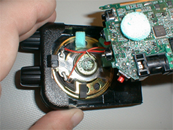
| 2) Once you have removed the back from the pager, you need to remove the circuitry from the front housing. This MUST be done carefully. You may damage your pager if this is not done correctly. |
 |
||
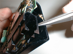
| 3) If the circuit boards do not come out freely, use your Tweezers between the Front housing and the battery compartment. Pry in an upwards direction, once it's raised slightly (as pictured) you can then hold the boards in your hand and pull the circuitry away from the front housing. |
 |
||
| 4) Use pliers to remove the clamp from the speaker. This is done by both pressing down and sliding the clamp counterclockwise with your pliers (as pictured). There are 3 points at which you can perform this operation though we find the point indicated to be the best to remove the clamp. | |||
 |
 |
||
| 5) To reassemble the pager place the speaker into its slot making sure that the speakers solder points are at the top closest to the knobs (as pictured). Reinstall the Speaker Clamp. This is done by aligning all three points of the clamp just to the side then pressing down and rotating the clamp clockwise at the same time. |
 |
||
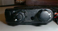
| 7) Next you need to Align the Knobs on the circuit board with the knobs on the housing. There is an easy way to do this if the knobs became mis-aligned. On the Housing Align the ABCD knob to the A position and align the Volume to the OFF Position. On the Circuit board turn both knobs fully counter clockwise, you should now be re-aligned. | |||
 |
 |
||
| 8) Once the knobs are aligned, insert the circuitry into the housing. This is usually done at a slight angle. When placing the circuit board into the front housing, extreme care is necessary. Be careful of the transistor pictured as it can hit the housing and will break the pager if damaged. |
 |
||
| 9) Once you have inserted the circuitry into the front housing, all that is left is to replace the back housing, install the screw and replace the battery door. |
 |
||
 |
 |
||
| Warning: We provide no technical support beyond this web page. If you attempt this procedure we will not assist you in any way, either on the phone or by e-mail. Proceed at your own risk! | |||

Copyright © 1997-2024
Paging & Wireless Service Center. All rights reserved.
Legal Information
Last updated on
06/12/24.